First images from the Light Microscopy Module (LMM)
We have 15 samples in the holder in this set of experiments, and our first task is to image all of the samples with the lowest-magnification microscope objective lens (2.5x). This lens’s magnification is ideal for the task, as it gives an image of each entire sample well. We first use brightfield transmission illumination (50/50 filter), where the intensity of the image is proportional to the amount of light passing through different parts of the sample. Thus, magnetic stir bar appears dark, as it transmits no light, and the glass appears bright, as most of the light passes through. Bubbles act as mini-lenses, and therefore are bright in the center and dark around their edges; the light from the edges is bent toward the center (or focused) by the bubble. These features are evident in an image of well number 5, containing a phase-separating sample, as shown in the image on the left.
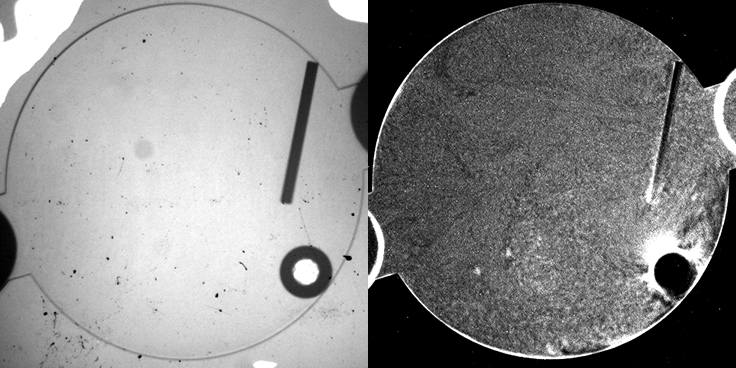
The image on the right is the same sample and position, but collected in fluorescence mode, where the intensity is proportional to the number of (fluorescent particles). Interestingly, we observe higher concentrations of particles aggregating around the edges of the sample chamber, the stir bar and the bubbles. Neither the stir bar nor bubble contain any fluorescent particles, and like the background glass appear black.
Compositing images to get a higher-magnification view of the entire sample
The 2.5x images are good to show the entire sample, but the resolution is limited. To get a higher-resolution view of the sample, we switch to a higher-magnification objective lens; however, the tradeoff is that the field of view is curtailed, and only part of the sample fits into the visible field of view. Fortunately, the LMM has an automated stage, so that the position of the sample visible to the microscope can be controlled remotely. As a result, we can take images in a tile-pattern that cover the entire sample:
The different fluorescence images are the tiled composite image taken at different depths from the cover slip inside the sample. If you look at the stir bar, you can see how different parts of the bar come into “focus” in the different images, giving an indicator of the depth within the sample from which the images are collected.
Each “tile” is a bit darker to the left, so that the rectangles representing each individual 10x image are easily seen. This is a result of uneven illumination; the samples are illuminated by light from a lamp, which does not cover the sample evenly (which might be ameliorated by changing internal microscope aperture settings).
But we have another way we might correct for this problem: a couple of our samples are fluorescent dye dispersed in a solvent inside identical sample wells—physically, the intensity of fluorescence should be completely even / isotropic, so any unevenness in the image should be caused by the illumination. By taking images under identical conditions of both the phase-separating sample of interest, and of the even dye solution, we should be able to cancel the background and see the sample without the effects of the uneven lamp illumination. So we will be testing this in upcoming operations.
Meanwhile, next stage is to look at higher-magnification, where we seek to understand the details of small portions of the sample, and see the behavior of these colloid structures up close.